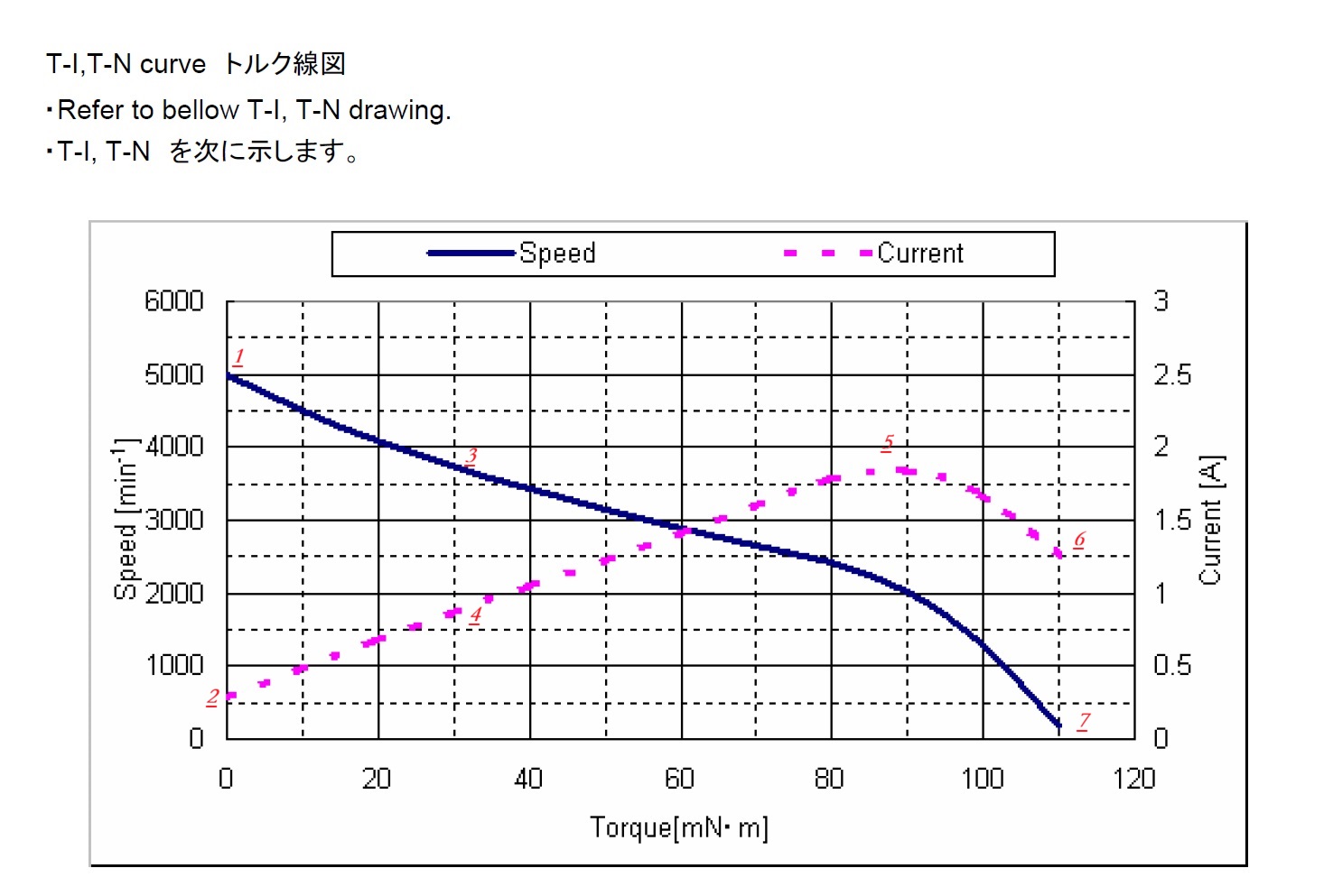
By analyzing the trends of the blue solid line (Speed) and the pink dashed line (Current) in the chart, the operational characteristics and performance boundaries of the motor under different loads can be extracted. The following is a detailed data interpretation corresponding to the rated voltage:
- Marker 1: Represents the maximum speed the motor can achieve under no load. Referred to as the "no-load speed", approximately 5000 rpm.
- Marker 2: Represents the current consumed by the motor under no load. Referred to as the "no-load current", approximately 0.25 A.
- Markers 3 and 4: Indicate that as the external torque increases, the motor speed decreases non-linearly. For example, Markers 3 and 4 represent a load of about 30 mN·m, where the motor speed is approximately 3700 rpm and the current is about 0.7 A. Output Power = 30 * 3700 / 9550 = 11.6 W Input Power = 24V * 0.7A = 16.8 W Motor Efficiency = Output Power / Input Power * 100% = 69% (Since the current values on the curve are typically labeled higher than actual values, the real motor efficiency would be higher than 69%).
- Marker 5: The current reaches its peak, approximately 1.8 A. This value is often used for designing the current margin of the power supply and drive circuit to prevent overload burnout.
- Marker 6: The motor's stall current, approximately 1.25 A.
Note: Typically, the stall current of a DC brushless motor is the maximum value. However, to prevent overheating and burnout, the drive chip integrates cycle-by-cycle hardware current limiting protection. A hardware comparator directly monitors the voltage drop across a sense resistor. Once it exceeds the set threshold, the MOSFET is turned off in the next PWM cycle, effectively preventing chip damage from overheating.
- Marker 7: The motor's stall torque, approximately 115 mN·m.
Author's Note: The current curves provided by motor manufacturers are generally higher than the actual values. This is primarily to serve as a reference for users when selecting an appropriately sized power supply, representing a conservative engineering design based on reliability, safety, and system considerations.
Motor Output Power Calculation Formula: P = T × n / 9550
- P: Output power, unit is Watts (W)
- T: Output torque, unit is millinewton-meters (mN·m)
- n: Speed, unit is revolutions per minute (rpm)
Motor Input Power Calculation Formula: P = U × I
- U: Operating voltage (V)
- I: Operating current (A)