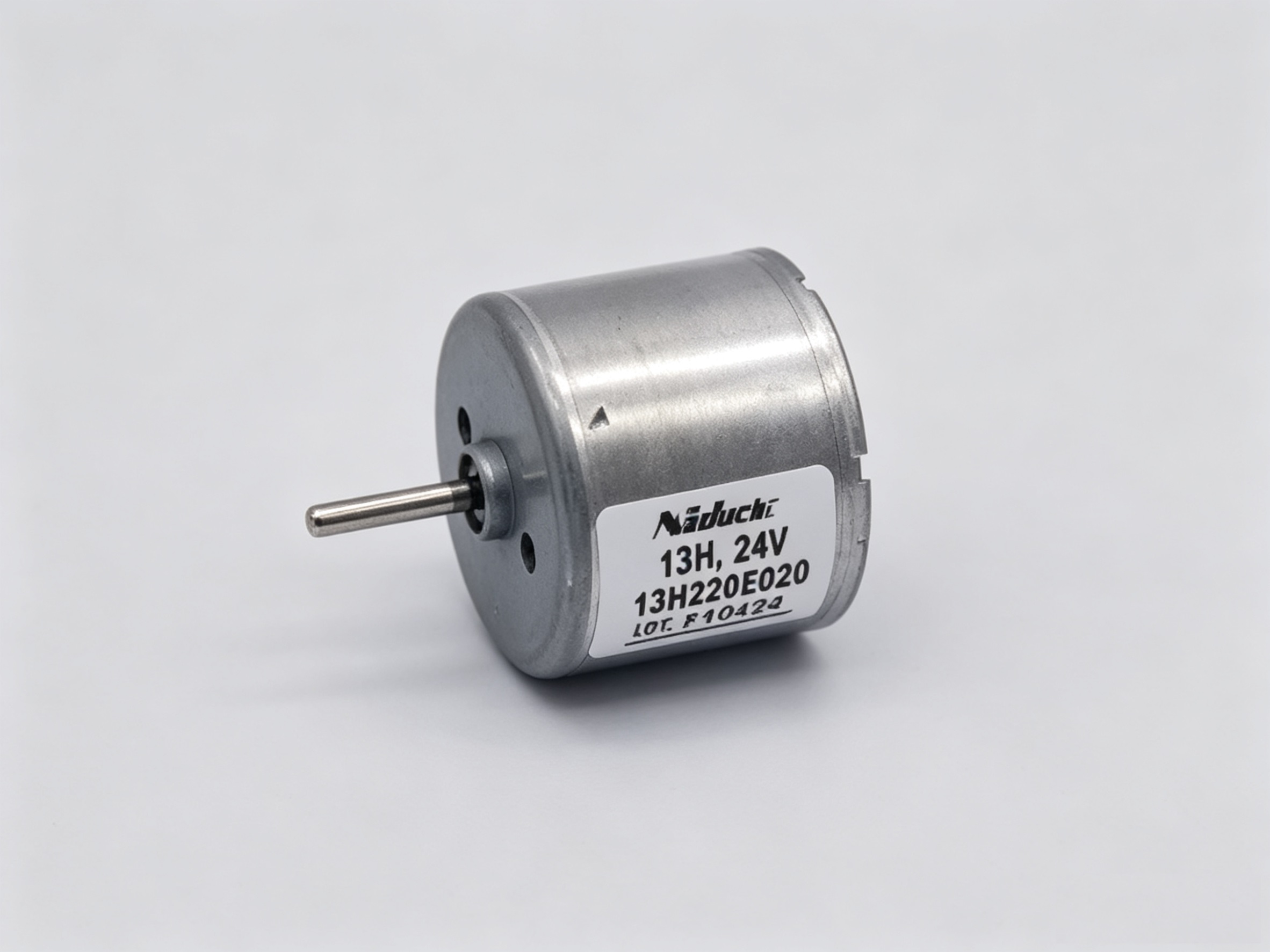
NIDEC 13H Series DC Brushless Motor Features:
- Clockwise rotation (CCW optional)
- Signal function available
- Locked-rotor protection
- Low inertia
- Quiet operation
- Compact case: ∅24.2 × 19.1 mm
- Output power: <3W
- Motor with built-in drive circuit (Please refer to the downloadable documentation for the motor's electrical characteristics and dimensions.)
Standard Models for the NIDEC 13H Series DC Brushless Motor:
- 12V Standard Model: 13H220E011
- 24V Standard Model: 13H220E020
About the FG Signal of the DC Brushless Motor
The FG signal output from the NIDEC 13H series DC brushless motor is a speed feedback signal. The FG terminal provides 6 pulses per motor revolution. This signal can be used both for real-time motor speed detection and as a feedback signal for the control system to achieve precise speed closed-loop control. Utilizing the FG signal for control enables stable motor operation across a wide speed range, from low speeds of several tens of RPM up to the motor's maximum speed.
Many users have reported that when reducing motor speed via PWM signals, the output torque at low speeds is significantly low. This is primarily because PWM speed control essentially reduces the average input voltage to the motor by adjusting the duty cycle, which consequently decreases the motor's driving capability. By acquiring the FG signal to monitor the actual motor speed in real time, closed-loop feedback can be established. This allows for dynamic adjustment of the control signal, thereby maintaining sufficient output torque even at lower speeds.
Extended Applications Utilizing the FG (Speed Feedback) Signal
Leveraging the pulse characteristics of the FG signal enables several extended applications, primarily including the following categories:
1. Precise Speed Closed-Loop Control
- Core Application: Using the FG signal as feedback to form a closed loop with a controller (e.g., PLC, microcontroller). The controller compares the set speed with the actual speed (calculated from the FG frequency) and dynamically adjusts the PWM duty cycle or drive current. This achieves high-precision constant speed operation, effectively countering load and voltage fluctuations.
2. Speed and Position Monitoring
- Speed Display and Monitoring: Connecting the FG signal to a tachometer or host computer software enables real-time digital speed display, recording, or overspeed/underspeed alarms.
- Simple Position Control and Counting: By counting FG pulses, the motor's cumulative revolutions or angle can be roughly calculated. This is useful for applications like simple fixed-length feeding or winding counting.
3. Multi-Motor Synchronization and Following
- Master-Slave Synchronization: Designating one motor as the master and inputting its FG signal as a reference to another (slave) motor's controller, forcing the slave to strictly follow the master's speed, achieving speed synchronization for multiple motors.
- Ratio Synchronization: The controller performs proportional calculation on the master's FG signal and uses the result as the speed setpoint for the slave, achieving synchronized operation at a fixed speed ratio (e.g., 1:2).
4. System Diagnosis and Protection
- Locked-Rotor and Stall Detection: Real-time monitoring of the FG signal. If the FG signal disappears or its frequency remains extremely low for an extended period while the drive signal is active, a locked-rotor or stall condition can be determined, triggering immediate protection and an alarm.
- Sudden Load Change Detection: By monitoring sudden changes in the FG signal frequency (non-commanded deceleration), a sudden increase in load can be indirectly sensed, which can be used to trigger corresponding handling processes.
5. Advanced Motion Control Integration
- Low-Cost Alternative to Encoder: In applications where extremely high precision is not required, the FG signal can act as a simple digital speed sensor, providing speed feedback for motion control cards or advanced drives, forming a cost-effective motion control system.
In summary, the FG signal is a key interface that converts the motor's physical motion into digital information. Its core value lies in enabling closed-loop control to enhance performance and precision. Building upon this, it extends to various advanced applications such as status monitoring, synchronization, coordination, and fault diagnosis, making it a crucial element for optimizing motor system functionality.