【Common Behavior and Engineering Challenges of Diaphragm Pump Membranes Under Low-Speed Operation】
Forcing a high-speed flexible diaphragm pump with a rated speed of 5000 RPM down to a "crawling" speed like 1 RPM, the diaphragm still undergoes deformation but struggles to produce an engineering-effective "suction and compression" action. This phenomenon does not stem from insufficient mechanical fit precision, but rather has the most direct causal link to the inherent physical properties of the rubber/plastic material.
Whether EPDM, NBR, or PTFE composite film, a diaphragm membrane is essentially not a rigid piston but a viscoelastic body. Under extremely low speeds (e.g., 1 RPM), the push rod slowly pushes the diaphragm upward into an arch. In this speed range, creep and stress relaxation effects of the elastomer dominate. Even as the motor turns a certain angle, the diaphragm may only develop a slight elastic bulge. Although the pump chamber volume changes, the pressure cannot accumulate enough to overcome the threshold to open the outlet check valve—due to the slight compressibility of the liquid itself and the static friction resistance of the valve element. The result: the motor keeps doing work, the diaphragm keeps deforming, yet the liquid only undergoes weak internal circulation inside the chamber without being truly expelled; its effective displacement effectively drops to zero.
In conventional diaphragm air or water pumps, sealing between the rubber diaphragm and the plastic framework/valve seat relies on compression set (interference fit) for passive sealing, not requiring "metal-grade" precision machined fits. However, when motor speed drops to 1 RPM, if the rubber’s recovery hysteresis is too large, the diaphragm cannot fully return to its original shape during reset, causing the effective displacement of the next stroke to decrease progressively. At this point, system repeatability deteriorates sharply. Actual performance often shows liquid flowing out intermittently in gulps, or even non-linear “skipping” phenomena like “the motor turns half a revolution with no water output, then suddenly spits out one large drop.” Thus, improving plastic housing machining tolerances cannot solve this problem—its root lies in the rubber compound’s dynamic modulus characteristics and the check valve’s opening/closing sensitivity.
【Diaphragm Motion Simulation and Test Methodology Based on Stepper Motor Drive】
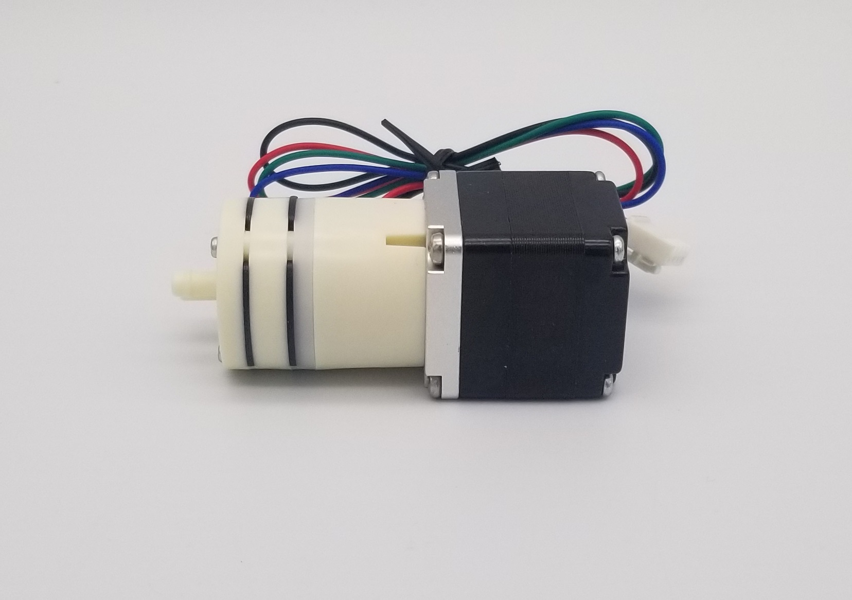
The NIDEC diaphragm pump employs a three-chamber (three-diaphragm) configuration with chambers spaced 120° apart. To simplify control, the author set the sampling interval to 20 seconds. Under an equivalent speed of 1 RPM, the motor rotates exactly 120° every 20 seconds, completing one full suction or discharge stroke of a single chamber per interval.
Since stable control of a BLDC motor down to 1 RPM is impractical, the original motor was replaced with a Size 28 hybrid stepper motor. The stepper motor provides precise angular positioning and stable low-speed operation even under open-loop control, meeting the experiment’s ultralow-speed drive requirements.
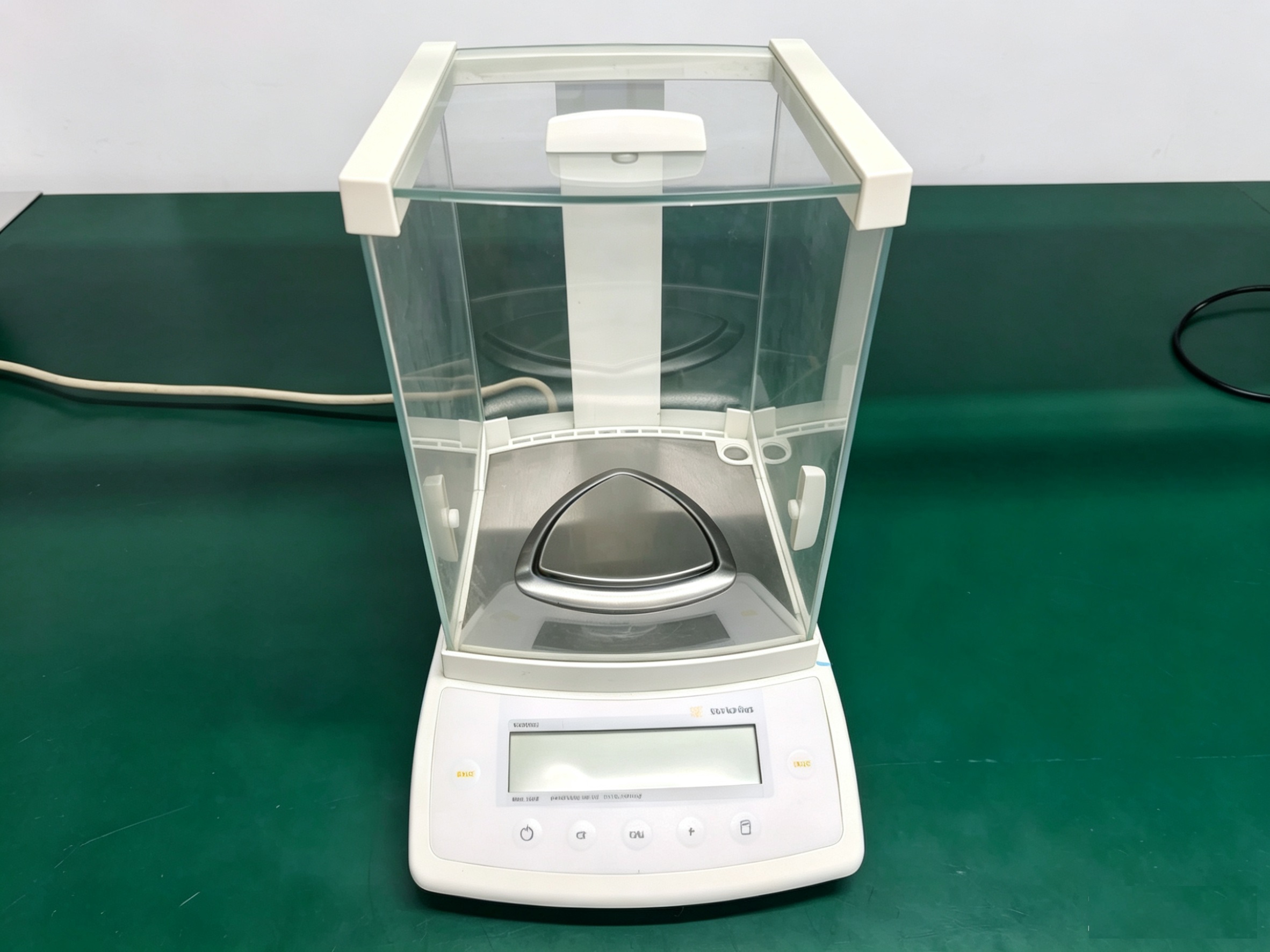
Because instantaneous flow rates are extremely small at such low speeds, traditional flow meters lack sufficient accuracy. Instead, this experiment uses a high-precision analytical balance with the gravimetric method: weight data is acquired in real time via data cable to a PC, enabling continuous, precise flow recording and analysis.
【Test Results Analysis and Diaphragm Performance Evaluation】
The following are the flow rate test data at motor speeds of 1 rpm, 2 rpm, 3 rpm, 5 rpm, 10 rpm, and 20 rpm respectively: (Medium: Water)
| No. | Test Time (s) | Flow Rate @ 1 rpm (ml/min) | Flow Rate @ 2 rpm (ml/min) | Flow Rate @ 3 rpm (ml/min) | Flow Rate @ 5 rpm (ml/min) | Flow Rate @ 10 rpm (ml/min) | Flow Rate @ 20 rpm (ml/min) |
|---|---|---|---|---|---|---|---|
| 0 | 0 | 0.0000 | 0.0000 | 0.0000 | 0.0000 | 0.0000 | 0.0000 |
| 1 | 20 | 0.1202 | 0.2437 | 0.3690 | 0.6101 | 1.2069 | 2.3432 |
| 2 | 40 | 0.1205 | 0.2473 | 0.3690 | 0.6116 | 1.2062 | 2.3199 |
| 3 | 60 | 0.1193 | 0.2439 | 0.3730 | 0.6098 | 1.2050 | 2.3210 |
| 4 | 80 | 0.1199 | 0.2447 | 0.3692 | 0.6086 | 1.2144 | 2.3467 |
| 5 | 100 | 0.1194 | 0.2449 | 0.3691 | 0.6109 | 1.2010 | 2.3291 |
| 6 | 120 | 0.1205 | 0.2464 | 0.3725 | 0.6127 | 1.2030 | 2.3242 |
| 7 | 140 | 0.1204 | 0.2445 | 0.3684 | 0.6192 | 1.2037 | 2.3216 |
| 8 | 160 | 0.1202 | 0.2445 | 0.3671 | 0.6122 | 1.2183 | 2.3530 |
| 9 | 180 | 0.1198 | 0.2433 | 0.3656 | 0.6099 | 1.2043 | 2.3230 |
| 10 | 200 | 0.1220 | 0.2468 | 0.3667 | 0.6092 | 1.2080 | 2.3279 |
| 11 | 220 | 0.1206 | 0.2434 | 0.3709 | 0.6157 | 1.2188 | 2.3279 |
| 12 | 240 | 0.1211 | 0.2433 | 0.3667 | 0.6063 | 1.2069 | 2.3490 |
| 13 | 260 | 0.1213 | 0.2462 | 0.3685 | 0.6070 | 1.2060 | 2.3214 |
| 14 | 280 | 0.1202 | 0.2433 | 0.3702 | 0.6074 | 1.2030 | 2.3249 |
| 15 | 300 | 0.1208 | 0.2422 | 0.3668 | 0.6132 | 1.2159 | 2.3289 |
| 16 | 320 | 0.1208 | 0.2430 | 0.3665 | 0.6082 | 1.2051 | 2.3418 |
| 17 | 340 | 0.1218 | 0.2457 | 0.3666 | 0.6097 | 1.2059 | 2.3231 |
| 18 | 360 | 0.1205 | 0.2426 | 0.3705 | 0.6103 | 1.2057 | 2.3290 |
| 19 | 380 | 0.1208 | 0.2448 | 0.3673 | 0.6159 | 1.2148 | 2.3299 |
| 20 | 400 | 0.1207 | 0.2446 | 0.3657 | 0.6114 | 1.2054 | 2.3450 |
| 21 | 420 | 0.1224 | 0.2468 | 0.3653 | 0.6112 | 1.2067 | 2.3277 |
| 22 | 440 | 0.1210 | 0.2463 | 0.3698 | 0.6082 | 1.2152 | 2.3258 |
| 23 | 460 | 0.1207 | 0.2455 | 0.3650 | 0.6177 | 1.2056 | 2.3187 |
| 24 | 480 | 0.1225 | 0.2490 | 0.3653 | 0.6097 | 1.2041 | 2.3518 |
| 25 | 500 | 0.1209 | 0.2479 | 0.3667 | 0.6096 | 1.2036 | 2.3304 |
| 26 | 520 | 0.1214 | 0.2477 | 0.3701 | 0.6101 | 1.2163 | 2.3248 |
| 27 | 540 | 0.1218 | 0.2471 | 0.3683 | 0.6160 | 1.2039 | 2.3481 |
| 28 | 560 | 0.1223 | 0.2509 | 0.3700 | 0.6108 | 1.2070 | 2.3276 |
| 29 | 580 | 0.1213 | 0.2472 | 0.3701 | 0.6087 | 1.2156 | 2.3221 |
| 30 | 600 | 0.1211 | 0.2468 | 0.3713 | 0.6107 | 1.2067 | 2.3236 |
| 31 | 620 | 0.1208 | 0.2477 | 0.3713 | 0.6158 | 1.2031 | 2.3546 |
| 32 | 640 | 0.1232 | 0.2483 | 0.3710 | 0.6086 | 1.1964 | 2.3206 |
| 33 | 660 | 0.1210 | 0.2452 | 0.3740 | 0.6098 | 1.2126 | 2.3240 |
| 34 | 680 | 0.1216 | 0.2472 | 0.3708 | 0.6094 | — | 2.3275 |
| 35 | 700 | 0.1222 | 0.2490 | 0.3705 | 0.6143 | — | 2.3565 |
| 36 | 720 | 0.1222 | 0.2445 | 0.3701 | 0.6086 | — | 2.3240 |
| 37 | 740 | 0.1200 | 0.2464 | 0.3722 | 0.6081 | — | 2.3240 |
| 38 | 760 | 0.1214 | 0.2459 | 0.3686 | 0.6137 | — | 2.3524 |
| 39 | 780 | 0.1228 | 0.2466 | 0.3679 | 0.6070 | — | — |
| 40 | 800 | 0.1202 | — | 0.3672 | 0.6077 | — | — |
| 41 | 820 | 0.1207 | — | 0.3703 | — | — | — |
| 42 | 840 | 0.1226 | — | 0.3666 | — | — | — |
| 43 | 860 | 0.1202 | — | 0.3668 | — | — | — |
| 44 | 880 | 0.1204 | — | 0.3699 | — | — | — |
| 45 | 900 | 0.1210 | — | — | — | — | — |
| 46 | 920 | 0.1219 | — | — | — | — | — |
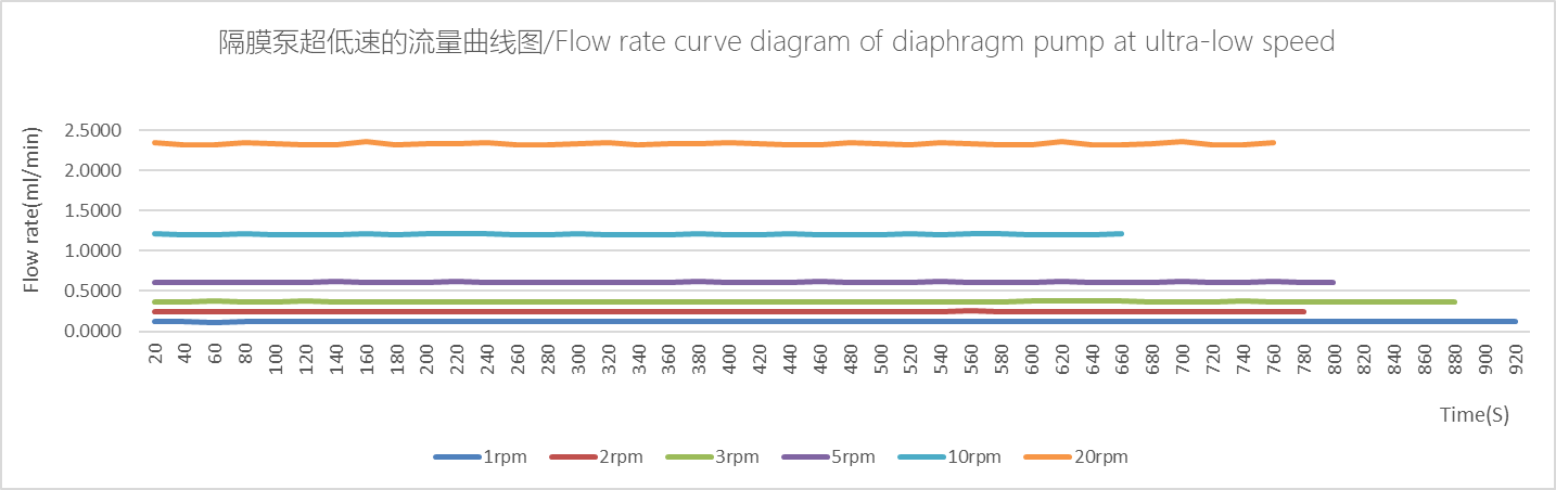
Surprising Repeatability
The most striking finding here is the repeatability. In fluid machinery involving rubber/silicone components, keeping flow fluctuation within ±2% is already considered excellent. Yet at ultralow speeds like 1–5 RPM, large fluctuations are typical.
- At 1 RPM (extremely stable): Values fluctuate between 0.1193 and 0.1220 ml/min. Max variation ≈ (0.1220−0.1193)/0.1207 ≈ 2.2%. This means every 120° rotation (every 20 s), the expelled liquid volume remains nearly constant—a testament to the stepper motor’s precise step-angle control.
- Full-range ripple pattern: The data in each column shows a subtle wave-like undulation. For example, at 1 RPM: 0.1202 → 0.1205 → 0.1193 → 0.1194 → 0.1205… This reflects the three-chamber alternating operation. Peaks likely correspond to moments just after a chamber completes exhaust (smoothest motion); troughs occur during transition to the next chamber or initial compression where minor hysteresis appears. Despite this periodic ripple, the extremely small peak-to-valley difference confirms very consistent chamber-to-chamber uniformity.
Linearity Analysis: Near-Perfect Proportionality
Ideally, diaphragm pump flow should be proportional to rotational speed. Check the data:
- Avg. flow @ 1 RPM ≈ 0.1207 ml/min
- Avg. @ 2 RPM ≈ 0.2442 ml/min (ideal 0.2414, deviation +1.1%)
- Avg. @ 3 RPM ≈ 0.3684 ml/min (ideal 0.3621, deviation +1.7%)
- Avg. @ 5 RPM ≈ 0.6108 ml/min (ideal 0.6035, deviation +1.2%)
From 1 to 5 RPM, flow and speed show excellent linearity. The stepper motor’s motion profile and torque ensure each diaphragm compression delivers consistent force.
Physical Implications Behind the Data
Does each diaphragm action at ultralow speed still produce effective suction/compression?
The data says yes—with remarkable efficiency.
At 1 RPM, ~0.12 ml is discharged every 20 s ⇒ each single-chamber stroke displaces roughly 0.04 ml. Had there been no effective compression, readings would be zero or wildly unstable; instead, the steady positive values prove the diaphragm retains its “volumetric displacement” function even at near-static speeds.
【Author’s Closing Remarks】
Given the NIDEC diaphragm pump’s high repeatability demonstrated here, can it be used as a metering pump?
The answer is no.
In the author’s view, a true metering pump requires more than just stability step-by-step during continuous running—it demands reproducibility across start/stop cycles and varying field conditions + traceable measurement accuracy. The structural and working principles of a diaphragm pump impose fundamental limits:
- The elastic umbrella/duckbill valve’s cracking behavior is deterministic, but its cracking pressure varies with material tolerance, aging, and surface stiction (stick-slip), making absolute starting flow unrepeatable across restarts.
- Air trapped in internal dead volumes can be neglected during a single continuous lab weigh‑in, but becomes an uncontrollable variable in real‑world usage where priming/venting conditions differ each time.
- This experiment confirms the NIDEC diaphragm pump can handle micro‑volume transfer of media, but using it for certified metering applications requires caution—or better, selection of a purpose‑built metering pump.