Some users have reported instances of motor burnout in 24V 13H series motors and 24V 00H series diaphragm pumps.
Setting aside motor burnouts caused by human factors such as incorrect wiring or excessive supply voltage, the primary burnouts are mainly due to scenarios often overlooked by most users: mechanical switch closure, live plugging/unplugging, and failures caused by N-type or P-type MOSFET control.
The specified supply voltage for the 24V 13H and 00H series is below 26.4V. The driver ICs used—LV8827 (by ON Semiconductor) and B063006 (by Rohm)—have rated voltages of 36V and 33V, respectively.
Whether it's mechanical switch operation, live connection/disconnection, or the fast switching of MOSFETs (N-type or P-type), surge voltage is highly likely to occur when controlling inductive loads or in the presence of parasitic inductance in the circuit. The essence of surge voltage is the induced voltage (V = -L * di/dt) generated across an inductor due to a rapid change in current (di/dt). Any switching action that causes a rapid make or break in the current path can lead to this issue. In practical applications, if the voltage exceeds the IC's specifications, it can cause IC failure:
- Mechanical Switches and Live Plugging/Unplugging: The rapid closing and opening of physical contacts lead to instantaneous current establishment or interruption, which most readily generates significant surge voltage and arcing.
- MOSFET Switch Control: MOSFETs are voltage-controlled devices, and their gate control can be very fast. Rapid changes in the gate voltage cause the MOSFET's drain-source channel to turn on or off quickly, similarly resulting in severe current fluctuations (high di/dt) in the main circuit. Therefore, both N-MOS and P-MOS face the same risk of surge voltage when used as switches. The level of risk depends not on the type of MOSFET, but on the nature of the switched load (whether it is inductive, like a motor or relay coil) and the parasitic inductance from the circuit layout.
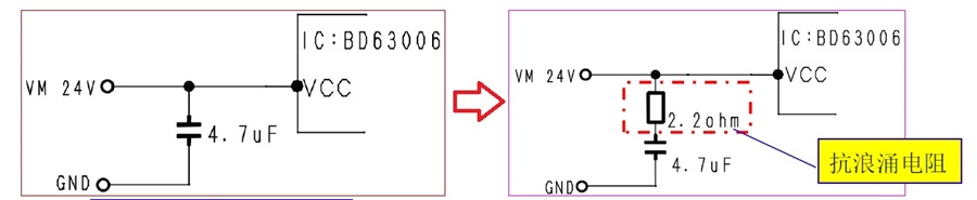
Considering that users often use mechanical switches during incoming inspection, occasional oversights by some operators in forgetting to power off, and cases where users previously used MOSFET switches to control DC brushed motors and are now applying them to DC brushless motors, NIDEC has implemented a modification to reduce potential losses for users in these scenarios: a resistor has been added in series with the capacitor in the drive circuit to suppress/absorb surge voltage.
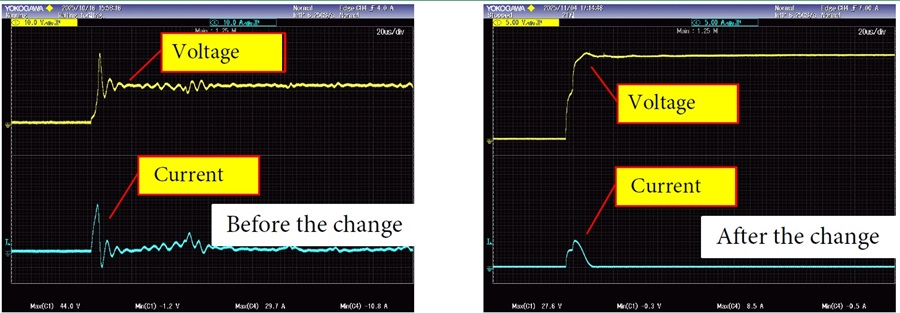
[Test Results]
The modified specification shows a significant improvement in surge voltage suppression, reducing the voltage to a safe range.
[Effect Follow-up]
Currently, there are no market reports of motor burnout for the 13H series motors and 00H series diaphragm pumps. The author has also conducted thousands of tests involving live wire connection/disconnection (producing sparks), with no burnouts occurring.
Note: Affected models (post-change) include: 13H162D010, 13H162E060, 00H220H043, 13H220E020, 13H162H030, 00H220H042, 00H220H032, 00H220H035, 13H101C010, 13H055C021, 13H055D020, 13H069H030, 13H266C081, 13H301P010, 13H301H010, 13H301G010, 13H308D040, 13H186C060, 00H704K200, 00H704K201, 13H838N030