
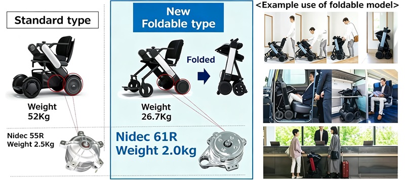
For electric wheelchair applications, Nidec has officially launched the upgraded model 61R (gear ratio 1/25) to replace the older model 55R (gear ratio 1/20.235). The new motor focuses on improving low-speed, high-torque performance and optimizing energy efficiency, while maintaining or even reducing its size and weight. This makes it better suited to meet the requirements of modern electric wheelchairs in terms of hill-climbing ability, driving range, and control precision.
Core Electrical and Performance Parameter Comparison (Rated Basis: DC 24V / 150W)
The following table summarizes the differences in key performance indicators between the old and new motor models (Test drive method: 55R uses square wave drive, 61R uses sine wave drive):
| Parameter Item | 55R (Old Model, Gear Ratio 20.235) | 61R (New Model, Gear Ratio 25) | Change Interpretation |
|---|---|---|---|
| Max Continuous Torque | 7.7 N·m | 14 N·m | Significant improvement (+82%), stronger hill climbing and heavy-load start/stop capability |
| Max Continuous Speed | 182 min⁻¹ | 123 min⁻¹ | Increased gear ratio reduces output speed, meeting wheelchair safe speed requirements |
| Max Continuous Current | 8.7 A | 10 A | Normal current increase due to higher torque |
| No-Load Speed | 218 min⁻¹ | 170 min⁻¹ | Natural result of gear ratio adjustment |
| No-Load Current | 2.5 A | 1 A | Lower losses, longer standby and cruising range on flat roads |
| Stall Torque (MAX) | 78.5 N·m | 35 N·m | Note: 61R table labels as MAX torque, strategy may lean toward protection |
| Stall Current | 67.8 A | — (Not specified) | - |
| Terminal Resistance | 0.1 Ω | 0.084 Ω | Slightly reduced internal resistance, marginally improved conduction efficiency |
| Pole/Slot Configuration | 10P12S | 8P12S | Magnetic pole optimization, adapted for sine wave drive to reduce torque ripple |
| Bearings | Rolling bearings | Rolling bearings | Consistent |
| Encoder / Sensor | None / 3 Hall IC | None / 3 Hall IC | Both rely on Hall sensors for rotor position feedback |
| Motor Weight | 2500 g | 2000 g | Weight reduction of 500g, contributing to overall vehicle lightweighting |
| Test Drive Method | Square wave drive | Sine wave drive | 61R adopts more advanced sine wave drive for quieter and smoother operation |
Performance Trend Summary
- 55R: Geared toward high-speed applications, with a wider continuous drive region but higher no-load current.
- 61R: By increasing the gear ratio (20.235 → 25), torque is nearly doubled, while no-load current is significantly reduced. The efficiency curve performs better in the low-speed, high-torque region, and the overall weight is lighter, making it highly suitable for real-world electric wheelchair operating conditions.
61R Motor Interface and Pin Definitions (Two Optional Configurations)
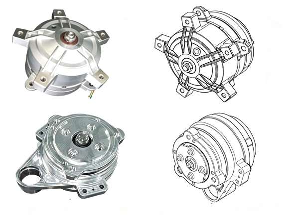
The new model 61R offers Option A and Option B connector configurations, which differ primarily in bracket design and pin arrangement, allowing customers to choose based on their vehicle wiring requirements.
General Electrical Characteristics (Applicable to Both Options)
- Motor Drive Voltage: Three-phase windings (U/V/W) support 16~48 V DC wide voltage input.
- Hall Sensor Power Supply: VCC range 3~5.5 V, Hall output is a digital signal from 0 to VCC, maximum output current ±1 mA.
- Brake Control: Equipped with BRAKE+ / BRAKE− output signals for electromagnetic brake drive.
- Temperature Detection: Built-in thermistor; TH pin outputs an analog voltage that varies with temperature (approximately 2.5 V at 25°C, approximately 0.46 V at 80°C, based on 3.3 V supply typical values), enabling the controller to monitor motor temperature rise.
Option A (Separate Connector Type: 8-Pin Signal Connector + 3-Pin Power Lines)
Option A separates the power lines (3-pin) from the signal lines (8-pin). The signal connector pin definitions are as follows:
| Pin | Signal Name | Wire Color | I/O | Remarks |
|---|---|---|---|---|
| 1 | U_WINDING | Red | I/O | 16~48 V, U phase output |
| 2 | V_WINDING | White | I/O | 16~48 V, V phase output |
| 3 | W_WINDING | Black | I/O | 16~48 V, W phase output |
| 1* | VCC | Red | IN | 3~5.5 V, Power supply |
| 2* | U_HALL | Yellow | OUT | 0~VCC, U phase Hall signal |
| 3* | W_HALL | Blue | OUT | 0~VCC, W phase Hall signal (±1 mA) |
| 4* | V_HALL | Green | OUT | 0~VCC, V phase Hall signal (±1 mA) |
| 5* | SIGNAL GND | Black | IN | Signal ground |
| 6* | BRAKE+ | White | OUT | Brake positive |
| 7* | BRAKE− | Brown | OUT | Brake negative |
| 8* | TH | Gray | OUT | Temperature detection analog signal |
Summary and Selection Recommendations
Upgrade Value
With a 20% weight reduction, the 61R achieves nearly double the continuous torque and lower no-load current. Combined with sine wave drive, it can significantly improve the driving comfort and driving range of electric wheelchairs.
Interface Flexibility
The two connector options accommodate different customer wiring harness design preferences. However, please note that the pin definitions and voltage characteristics of the old and new models cannot be directly interchanged. When replacing the motor, the controller parameters must be re-verified.
For More Information
If you require more detailed information, including motor performance curves, dimensional drawings, environmental ratings, and other complete product specifications, please leave a message or contact the blog author via email.
Let me know if you need any adjustments or would like this formatted differently for a specific use case (e.g., datasheet, brochure, website).