
Sensorless Control Logic for Brushless DC Servo Motor
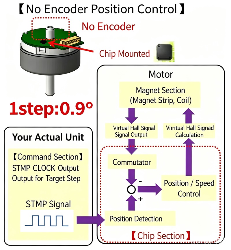
Hardware Architecture and Key Parameters
- Sensorless Design: The motor has no encoder and no internal Hall sensors, eliminating physical position feedback components.
- Onboard Chip Integration: A control chip is integrated inside the motor (the "chip section" indicated by the red dashed box in the diagram), responsible for executing servo algorithms, position estimation, and closed-loop control. Highly integrated, no external driver required.
- High-Precision Microstepping: 1 step = 0.9°, meaning each pulse from the host controller moves the motor by 0.9° (400 pulses per revolution), achieving high-resolution positioning.
- Magnetic Section: Composed of magnetic strips (rotor permanent magnets) and coils (stator windings), serving as the physical carrier for power output and position signal detection.
Control Logic Flow
1. Command Input (Host Machine)
- STMP CLOCK Output at Target Stage: The host (e.g., PLC or microcontroller) sends STMP signals (pulse square waves) and direction commands to the motor.
- Function: Sets the "target position" or "number of steps" for the motor. The control method is similar to that of a stepper motor.
2. On-Chip Sensorless Closed-Loop Operation (Chip Section)
After receiving the command, the built-in chip uses the High-Frequency Injection (HFI) method to perform position estimation and closed-loop control:
- Position Command Calculation: Converts the received STMP pulse commands into an internal "target position value."
- Estimated Position Value / Virtual Hall Signal Output: (The chip injects high-frequency voltage signals into the stator windings, utilizes the rotor saliency effect, and demodulates the high-frequency current response to estimate the real-time rotor angle, converting it into a virtual Hall signal.)
- Position Detection and Deviation Comparison: Compares the "target position" with the "estimated position (virtual Hall signal)" (circle +/- symbol in the diagram) to obtain the position deviation.
- Position/Speed Control: Based on the deviation value, calculates the required speed and torque current using an internal PID algorithm.
- Inverter: Converts the control signals into three-phase drive currents and outputs them to the magnetic section.
3. Motor Execution and Feedback
- Sensorless Feedback Path: The motor itself has no physical sensor pins. The chip uses the HFI method to detect coil inductance/current changes online and estimates the position.
- Closed-Loop Correction: If load fluctuations cause the actual rotor position to deviate from the command, the chip detects the deviation in real time via HFI and automatically increases the output current (torque compensation), ensuring the motor accurately follows the command and preventing step loss.
Features and Applications
- Excellent Zero/Low-Speed Performance: HFI can effectively estimate the rotor position even when the motor is stationary or running at very low speeds, enabling zero-speed startup and high-torque control at low speeds.
- High Reliability and Low Cost: No encoder or Hall elements, reducing cost and size, and providing strong resistance to oil, vibration, and humidity.
- Extremely Simple Control: Only pulse + direction signals are needed externally; all closed-loop operations are completed automatically inside the chip.
- Application Scenarios: Ideal for medium-to-low-speed precision equipment requiring accurate angle/flow control with constraints on size and cost, such as medical infusion pumps, enteral feeding pumps, peristaltic pumps, small conveyors, and mixing devices.